

 > 제품소개 > Dimensional Tolerances
- ASME B16.9
- MSS SP-43
- KS/JIS
ASME B16.9
1. Wrought Steel Butt-Welding Fittings
| All fittings | 90˚and 45˚ Elbows |
Tees | Reducers | Caps | 180˚Returns | |||||
|---|---|---|---|---|---|---|---|---|---|---|
| Nominal Pipe Size |
Outside Diameter at Bevel OD |
Inside Diameter at End ID |
Wall Thickness T |
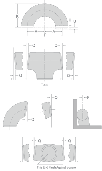
Center- to-End Dimension A,B |
Center- to-End Dimension C,M |
End to End H |
Back to Face E |
Center- to Center Dimension P |
Back to Face Dimension K |
Alignments of Ends K |
| ½~2½ | +0.06 -0.03 |
±0.03 | Not less than 87½% of nominal thickness |
±0.06 | ±0.06 | ±0.06 | ±0.12 | ±0.25 | ±0.25 | ±0.03 |
| 3~4 | ±0.06 | ±0.06 | ||||||||
| 5~8 | ±0.09 -0.06 |
±0.25 | ||||||||
| 10~18 | +0.16 -0.12 |
±0.12 | ±0.09 | ±0.09 | ±0.09 | ±0.38 | ±0.06 | |||
| 20~24 | +0.25 -0.19 |
±0.19 | ||||||||
| 26~30 | ±0.12 | ±0.12 | ±0.19 | ±0.38 | - | - | - | |||
| 32~48 | ±0.19 | ±0.19 | ||||||||
| Nominal Pipe Size |
Angularity Tolerance | |
|---|---|---|
| Off Angle Q |
Off Plane P |
|
| ½ ~ 4 | 0.03 | 0.06 |
| 5 ~ 8 | 0.06 | 0.12 |
| 10~12 | 0.09 | 0.19 |
| 14~16 | 0.25 | |
| 18~24 | 0.12 | 0.38 |
| 26~30 | 0.19 | |
| 32~42 | 0.5 | |
| 44~48 | 0.75 | |
MSS SP-43
| Nominal Pipe Size |
All Fittings | 90˚Elbow 45˚Elbow Tee |
Reducer Lap Joint Stub End |
180˚Return | |||
|---|---|---|---|---|---|---|---|
| Outside(1) Diameter at Welding End |
Wall Thickness |
Center-to-end Dimension A,B,C,M |
Overall Length F,H |
Center-to -Center Dimension O |
Center-to -Center Dimension K |
AlignMent of Ends U |
|
| ½ ~ 1½ | ±0.03 | Not less than 87½% of nominal thickness |
±0.06 | ±0.06 | ±0.25 | ±0.25 | ±0.03 |
| 2 ~ 3½ | ±0.03 | ±0.06 | ±0.06 | ±0.25 | ±0.25 | ±0.03 | |
| 4 | ±0.03 | ±0.06 | ±0.06 | ±0.25 | ±0.25 | ±0.03 | |
| 5 ~ 8 | +0.06 -0.03 |
±0.06 | ±0.06 | ±0.25 | ±0.25 | ±0.03 | |
| 10~18 | +0.09 -0.03 |
±0.09 | ±0.09 | ±0.38 | ±0.25 | ±0.06 | |
| 20~24 | +0.12 -0.03 |
±0.09 | ±0.09 | ±0.38 | ±0.25 | ±0.06 | |
| Nominal Pipe Size |
All Fittings | Cap | Lap Joint Stub End | ||
|---|---|---|---|---|---|
| Outside(1) Diameter at Welding End |
Wall Thickness |
Overall Length E |
Fillte(2) Radius Of Lap A |
Outside Diameter of Lap G |
|
| ½ ~ 1½ | ±0.03 | Not less than 87½% of nominal thickness |
±0.12 | +0 -0.03 |
+0 -0.03 |
| 2 ~ 3½ | ±0.03 | ±0.12 | +0 -0.03 |
+0 -0.03 |
|
| 4 | ±0.03 | ±0.12 | -0.06 | +0 -0.03 |
|
| 5 ~ 8 | +0.06 -0.03 |
±0.25 | -0.06 | +0 -0.03 |
|
| 10~18 | +0.09 -0.03 |
±0.25 | -0.06 | +0 -0.06 |
|
| 20~24 | +0.12 -0.03 |
±0.25 | -0.06 | +0 -0.06 |
|
· Dimensions are in inches.
Notes1.Out of roundness is the vector sum of the plus and minus tolerance.
2. Fillet B radius is the maximum.
KS / JIS
1. Steel Butt-Welding Pipe Fittings for Ordinary Use [KS B 1522 / JIS B 2311]
| Item | Type of Pipe Fitting |
Nominal Diameter | ||||
|---|---|---|---|---|---|---|
| ½ ~ 2½ | 3 ~ 4 | 5 ~ 8 | 10~18 | 20 | ||
| Tolerance | ||||||
| Outside Dia, at end face (OD) | All pipe Fittings |
±2 | ±2.5 | ±3.5 | +5 -4.5 |
+6.4 -4.8 |
| Inside Dia, at end face (ID) | ±2 | ±2.5 | ±3.5 | ±4.5 | ±4.8 | |
| Wall thickness(T) | +Not specified -15% |
|||||
| Center-to-end dimension (A,B) | 90˚Elbow 45˚Elbow |
±2.0 | ±3.2 | ±4.8 | ||
| Center-to-center dimension (P) | 180˚Elbow | ±6.4 | ±9.5 | - | ||
| Back-to-face dimension (K) | ±6.4 | - | ||||
| Alignment of ends(Max) (U) | 1.6 | 3.2 | - | |||
| End-to-end dimension (H) | Reducer | ±2.0 | ±3.2 | |||
| Center-to-end dimension (C.M) | Tee | ±2.0 | ±3.2 | |||
| Back-to-face dimension (E) | CAP | ±3.2 | ±6.4 | |||
2. Steel Butt-Welding Pipe Fittings for Special Use and Steel Plate Butt-Welding Pipe Fittings
[KS B 1541 / JIS B 2312 / KS B 1543 / JIS B 2313]
| Item | Type of Pipe Fitting |
Nominal Diameter | ||||||
|---|---|---|---|---|---|---|---|---|
| ½ ~ 2½ | 3 ~ 4 | 5 ~ 8 | 10~18 | 20~24 | 26~30 | 32~26 | ||
| Tolerance | ||||||||
| Outside Dia,at end face (OD) | All pipe Fittings |
+1.6 -0.8 |
±1.6 | +2.4 -1.6 |
+4 -3.2 |
+6.4 -4.8 |
||
| Inside Dia,at end face(ID) | ±0.8 | ±1.6 | ±3.2 | ±4.8 | ||||
| Wall thickness (T) | +Not specified -12.5% |
|||||||
| Center-to-end dimension (A.B) | 90˚Elbow 45˚Elbow |
±1.6 | ±2.4 | ±3.2 | ±4.8 | |||
| Center-to-center dimension (P) | 180˚Elbow | ±6.4 | ±9.5 | |||||
| Back-to-face dimension (K) | ±6.4 | |||||||
| Alignment of ends(Max) (U) | * ±0.8 ** ±1.6 |
* ±1.6 ** ±3.2 |
||||||
| End-to-end dimension (H) | Reducer | ±1.6 | ±2.4 | ±4.8 | ||||
| Center-to-end dimension (C.M) | Tee | ±1.6 | ±2.4 | ±3.2 | ±4.8 | |||
| Outside of end Peripheral length | All pipe Fittings | - | ±0.5 | |||||
* Application of KS B 1541, JIS B 2312
* Application of KS B 1543, JIS B 2313
· Dimesions are in millimeters.
3. Steel Socket-Welding Pipe Fittings for Special [KS B 1542 / JIS B 2316]
| Item | Type of Pipe Fitting |
Nominal Diameter | |||||||
|---|---|---|---|---|---|---|---|---|---|
| ⅛ and ¼ | ⅜ and ¾ | 1 to 2 | 2½ and 3 | ||||||
| Tolerance | |||||||||
| Inside Diameter of socket | All pipe Fittings |
+0.3 0 |
+0.4 0 |
||||||
| Bore diameter | ±0.4 | ±0.8 | |||||||
| Eccentricity of inside diameter of socket to bore diameter |
±0.8 | ||||||||
| Inclination of socket hole to fitting bore axis |
1.5/300 Max. | ||||||||
| Distance from center to bottom of socket |
45˚Elbow 90˚Elbow cross |
±0.8 | ±1.5 | ±2 | ±2.5 | ||||
| Laying length | Full coupling | ±1.5 | ±3 | ±4 | ±5 | ||||
| Laying length | Half coupling | ±0.8 | ±1.5 | ±2 | ±2.5 | ||||
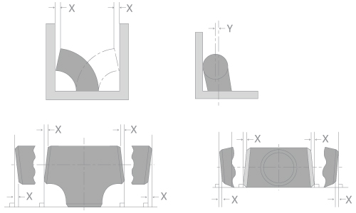
4. Right Angle for Shaft-Center of Pipe Fittings
[KS B 1522 / JIS B 2311 / KS B 1541 / JIS B 2312 / KS B 1543 / JIS B 2313]
| Item | Type of Pipe Fitting |
Nominal Diameter | |||||||
|---|---|---|---|---|---|---|---|---|---|
| ½ ~ 4 | 5 ~ 8 | 10~12 | 14~16 | 18~24 | 26~30 | 32~42 | 44~48 | ||
| Tolerance | |||||||||
| Off Angle (X) | All pipe Fittings |
0.8 | 1.6 | 2.4 | 3.2 | 4.8 | |||
| Off Plane (Y) | 1.6 | 3.2 | 4.8 | 6.4 | 9.5 | 12.7 | 19.1 | ||
 * Dimensions are in millimeters.

TEL 051-831-5131 FAX 051-831-5138E-mailwhb@winhibend.com
SEOUL OFFICE : 15104 경기도 시흥시 공단1대로 270 (시화공단 3다 201-2)TEL 031-431-5131 FAX 031-431-5138E-mailwhb@winhibend.com
copyright (c) 2016 WINHIBEND. ALL right reserved.